

Standards is the common methodology followed by all the developers or the manufactures of the hardware and software parts especially electronic parts is considered as the standards. Standards will follow mostly the same technology and some advance technologies but the output will be formed in common method.
In network, all the manufacturing companies follows the same method to follow a common standard and this will help for the network engineers and admin to find the errors and to reduce the expense and help for making an effective network connection by using different companies’ hardware. If the manufacturing companies doesn’t follow the same standards then the network engineers need to purchase the same brand hardware to form the network and this will reduce the efficiency and will cost high when try to change the one-part due to any failure or reason the network engineer should change all the other parts with the same brand to support the new parts.
The primary reason for standards is to ensure that hardware and software produced by different vendors can work together. Without networking standards, it would be difficult if not impossible to develop networks that easily share information. Standards also mean that customers are not locked into one vendor. They can buy hardware and software from any vendor whose equipment meets the standard. In this way, standards help to promote more competition and hold down prices.
In present, there are two types of standards are followed by the developers. Such as,
- Formal
- De facto
Formal standards
A formal standard is developed by an official industry or government body. For example, there are formal standards for applications such as Web browsers (e.g., HTTP, HTML), for network layer software (e.g., IP), data link layer software (e.g., Ethernet IEEE 802.3), and for physical hardware (e.g., V.90 modems). Formal standards typically take several years to develop, during which time technology changes, making them less useful.
De facto standards
De facto standards are those that emerge in the marketplace and are supported by several vendors but have no official standing. For example, Microsoft Windows is a product of one company and has not been formally recognized by any standards organization, yet it is a de facto standard. In the communications industry, de facto standards often become formal standards once they have been widely accepted.
Networking standards
In networking, there are many common formal standards are available in present world and this will be followed by the network engineers and also by the manufacturing companies of the hardware parts. According to this the most common standard are follows,
- Cabling standards
- OSI reference model
- TCP/IP standards
- IEEE Standard
Cabling standards
The latest of the Commercial Building Telecommunications Cabling Standard is according to the ANSI/TIA/EIA, includes T568A and T568B. The both standards are followed to make the RJ45 cablings. The most common standard among these two are T568B. These contain the information needed for designing, installing, and testing a general structured cabling system. The Telecommunication Industrial Association standard defines the restrictions for each part of the cabling system, which includes work area wiring, horizontal wiring, telecommunication closets, equipment rooms and cross- connects, backbone (vertical) wiring, and entrance facilities.
Mostly the both cabling styles are same only the connecting color order will vary and this was used to connect twisted pair cables which is used in the network with the RJ45 or Ethernet connector.
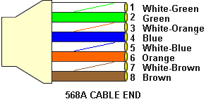
Color order of 568A cables The color order of the 568 A cables are follows
- White-Green
- Green
- White-Orange
- Blue
- White-Blue
- Orange
- White-Brown
- Brown
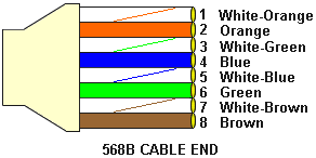
Color order of 568B cables The color order of the 568 B cables are follows
- White-Orange
- Orange
- White-Green
- Blue
- White-Blue
- Green
- White-Brown
- Brown
The most common standard cable is 568 B. When connecting the connectors in same order for both side the method of cable can be called as straight cables and when connecting the cables as one end in the method of 568 A and the other end as 568 B then the cable will be called as cross over cables.
The straight cables can be used to connect in different situations to transfer the data and the cross over will be used in other different situations.
The situation where the straight cables will be used,
- Connect a computer to a switch/hub’s normal port.
- Connect a computer to a cable/DSL modem’s LAN port.
- Connect a router’s WAN port to a cable/DSL modem’s LAN port.
- Connect a router’s LAN port to a switch/hub’s uplink port. (normally used for expanding network)
- Connect 2 switches/hubs with one of the switch/hub using an uplink port and the other one using normal port.
The situation where the cross over cables will be used,
- Connect 2 computers directly.
- Connect a router’s LAN port to a switch/hub’s normal port. (normally used for expanding network)
- Connect 2 switches/hubs by using normal port in both switches/hubs.
To make an Ethernet cable whether it is a cross over or straight the user should follow the below steps.
- Pull the cable off the reel to the desired length and cut. If you are pulling cables through holes, it’s easier to attach the RJ-45 plugs after the cable is pulled. The total length of wire segments between a PC and a hub or between two PC’s cannot exceed 100 Meters (328 feet) for 100BASE-TX and 300 Meters for 10BASE-T.
- Start on one end and strip the cable jacket off (about 1″) using a stripper or a knife. Be extra careful not to nick the wires, otherwise you will need to start over.
- Spread, untwist the pairs, and arrange the wires in the order of the desired cable end. Flatten the end between your thumb and forefinger. Trim the ends of the wires so they are even with one another, leaving only 1/2″ in wire length. If it is longer than 1/2″ it will be out-of-spec and susceptible to crosstalk. Flatten and insure there are no spaces between wires.
- Hold the RJ-45 plug with the clip facing down or away from you. Push the wires firmly into the plug. Inspect each wire is flat even at the front of the plug. Check the order of the wires. Double check again. Check that the jacket is fitted right against the stop of the plug. Carefully hold the wire and firmly crimp the RJ-45 with the crimper.
- Check the color orientation, check that the crimped connection is not about to come apart, and check to see if the wires are flat against the front of the plug. If even one of these are incorrect, you will have to start over. Test the Ethernet cable.